Combined Propellant/Pressurant Vessel (CPPV) Concept
Introducing Steelhead’s lightweight, low cost, simple and safe propellant concept
SECTION 1: BACKGROUND
A common design for launch/space (i.e., rocket) propulsion involves liquid propellants. In this application, often there is a gaseous pressurant stored in a Composite Overwrapped Pressure Vessel (COPV) at high pressure, and a diaphragm tank for the propellant. These diaphragm vessels have been in the market for decades and are a proven technology.
The gas stored in the pressurant tank is released into the propellant (or oxidizer) vessel and forces the propellant/oxidizer on one side of a diaphragm (acting as a barrier) and releases the propellant.
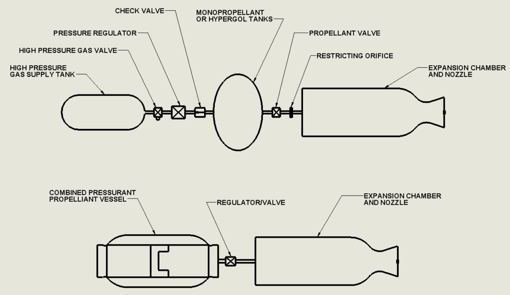
Figure 1. A liquid propellant-based propulsion system design, inclusive of a diaphragm-tank (center) for propellant storage and expulsion
The materials used for oxidizer and propellant are generally quite toxic, corrosive, caustic, often carcinogenic and have adverse material interaction effects. In the diaphragm application briefly described above, the material interaction is paramount and traditional elastomer materials do not work.
The ideal bladder materials would be chemically inert, impervious to the propellants and the pressurant, sufficiently strong and resistant to damage by repeated sharp creasing, and capable of fabrication into the shapes and stiffnesses needed to control folding. No such materials are available for most common propellants. JPL Technical Report 32-899
Thus tanks that need discharge or expulsion of propellants are complex, extremely expensive and in tight supply to the aerospace community. Elastomeric materials for diaphragm tanks which satisfy the compatibility with propellants are themselves proprietary. Tanks without a diaphragm require a Propellant Management Device (PMD), which are often complicated and expensive to reduce sloshing and provide propellant to the engine.
As there is increased attention in space launch, satellite launch etc., a new propellant tank designed is desirable with enhanced safety, increased simplicity and a much-reduced cost. Steelhead Composites offers this solution in a piston vessel which we call the Combined Pressurant/Propellant Vessel (CPPV).
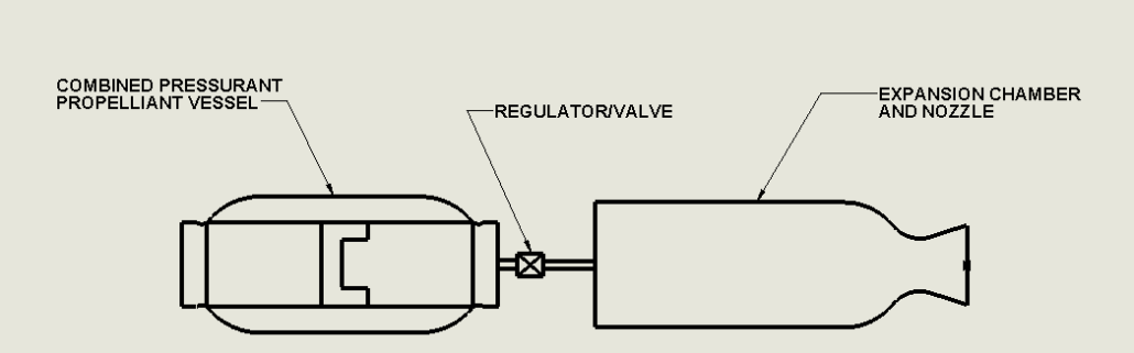
Figure 2. A simplified liquid propellant-based propulsion system design, inclusive of a Steelhead CPPC (left) for propellant storage and expulsion.
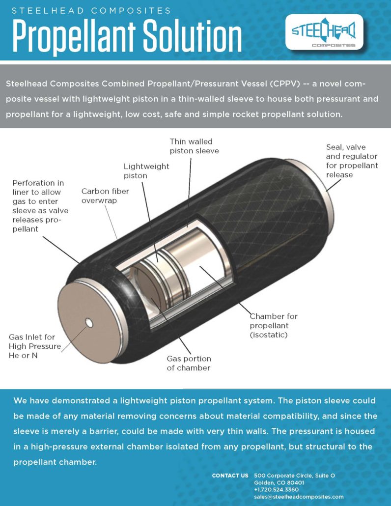
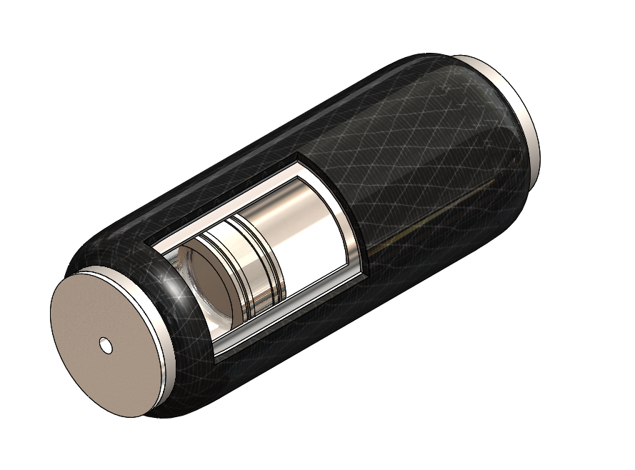
Our invention utilizes a composite pressure vessel body and a piston chamber that is disposed within the interior space of the vessel body (see cover page image). The piston chamber acts as a piston accumulator. However, unlike conventional pistons, the piston chamber does not require a thick steel cylindrical member to support the structural load. The majority of pressure exerted by the fluids in hydraulic pressure accumulator of the invention is carried by the vessel body and not the piston chamber itself.
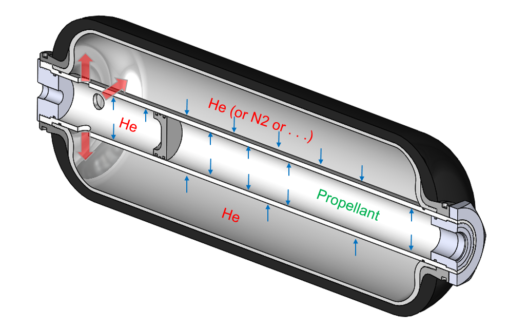
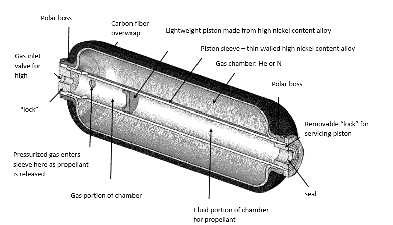
Figure 3. Cross-sectional Steelhead CPPV diagram.
SECTION 2: MOTIVATION
Diaphragm tanks have many advantages. First, they are easy to operate. Principally, the gaseous pressurant exerts pressure against the elastomeric diaphragm and expels liquid propellant through the outlet port. Second, diaphragm tanks are inherently reliable because of their operational simplicity. Third, unlike tanks containing surface tension propellant management devices (PMDs) that require extensive functional validation through analyses, there is no need to perform functional analysis for diaphragm tanks. For these reasons, diaphragm tanks are popular on many LEO, MEO, and exploration missions.
However, there are disadvantages to diaphragm tanks. First, as tank size grows in diameter or height, the diaphragm size must grow accordingly, and the mass increase might render the diaphragm tank option unattractive as compared to a PMD option. Second, there are size limitations. The current equipment produces diaphragms up to 1001 mm (39.4 in) in diameter and 613 mm (24.1 in) in height. Although it is possible to use a larger equipment to mold larger diaphragms, the mass penalty from the larger diaphragms usually does not favor this option. Review of ATK Diaphragm Tanks – 2018
There has been little motivation to innovate on diaphragm propellant tanks as they have a strong space legacy and a relatively few number of propellant tanks are demanded at any time. Steelhead decided to suggest our piston accumulator technology to the propellant market based on the following events:
- New propellant chemicals require interaction analysis with diaphragm materials and may not be compatible.
- We have received requests for lower cost propellant solutions
- Safety is paramount and our piston would be serviceable, unlike diaphragms and should be inherently safer.
- Design envelopes do not always favor the spherical shape of diaphragms
- A combined pressurant/propellant tank would alleviate needs for pumps, anti-sloshing devices and plumbing.
Steelhead Proposed Solution — use composite piston design to simplify the design, to house both the pressurant and propellant for either monopropellant systems or oxidizer as a simple, single solution.
In this concept, the piston sleeve could be made of any material removing concerns about propellant interaction. The sleeve could be made very thin wall and the piston light-weighted accordingly as it is merely a barrier.
The working gas (helium, nitrogen) would be pressurized in the external chamber will be in isostatic pressure with the propellant. The pressurant gas would be isolated from any propellant and the composite vessel would hold all of the pressure providing structural integrity during operation, thus a very intriguing rocket propellant tank.
The material compatibility issues would be decreased, safety increased, and it could simplify vessels by eliminating anti-slosh devices because the propellant/oxidizer would always be under pressure and gas free.
SECTION 3: TECHNICAL APPROACH
The concept of CPPV the lightweight combined propellant/pressurant tank with a piston is explained with the help of the figures and claims below:
The cylindrical piston chamber that houses the reciprocating piston is enclosed within a composite overwrapped pressure vessel (COPV). The reciprocating piston and piston sleeve can be made out of metal, composite, ceramic, reinforced polymer or a combination thereof, but can be lightweight and think walled. the large port opening COPV is the pressure holding structure. In case of COPV the port opening are facilitated by high strength polar boss integrated with the liner and composite structure; the cylindrical piston chamber is inserted into the pressure vessel through the port opening.
The piston chamber contains a compressible gas on one side, such as helium or nitrogen which is kept separate from the propellent by the reciprocating piston. The radial seals separates the pressurant and the propellant in the two compartments. After insertion inside the pressure vessel, the cylindrical piston chamber is sealed against the polar opening using radial seals. This prevents leakage of gas or fluid past the port opening of the pressure vessel. The annular area between the cylindrical piston chamber and the structural shell that is filled with the pressurant gas.
A communication pathway exists between the compartment containing compressible gas and the annular area between the piston chamber and the structural shell. This can be accomplished by allowing holes or slits in the piston chamber on the gas compartment side. The pressure in the compressed gas is structurally supported by the structural shell, a plastic/metal/no liner with composite reinforcement.
The reciprocating piston slides towards the gas compartment and compresses the gas when more propellant enters the piston compartment. The piston reciprocates immediately to compress the gas and bring equilibrium in pressure between the gas and fluid. Energy is stored in the compressed gas and when the valve opens for the propellant, the piston fills the gap to ensure that the pressure on the gas is always in equilibrium with the pressure of the propellant.
The cylindrical wall of the piston chamber is in neutral equilibrium since there is zero pressure differential between the inside and outside of the cylindrical chamber wall, thus the piston chamber can be made from thin walled metal, ceramic, polymer or composite to ensure material compatibility.
With this novel design, the internal diameter of the piston chamber can vary, allowing a differing ratio of pressurant to propellant, including to allowance of a very large (70-85%) piston sleeve compared to the internal diameter of the pressure vessel and thus a high volume of propellant.
Unlike monolithic and isotropic material like steel, a composite overwrapped pressure vessel with a large port opening can be designed to withstand very high internal pressure. This is enabled by an optimized design of the structural shape and composite layup such that the composite material is adequately and optimally placed to support the internal pressure
SECTION 4: TECHNOLOGICAL READINESS
The application of Steelhead’s CPPV from fluid power to space propulsion will require additional investment and investigation, in particular for sealants for the reciprocating piston. That said, for conceptual demonstration, we produced a prototype piston to test the design. For demonstration, we employed a test prototype and inserted a plastic piston sleeve with rubber stopper.
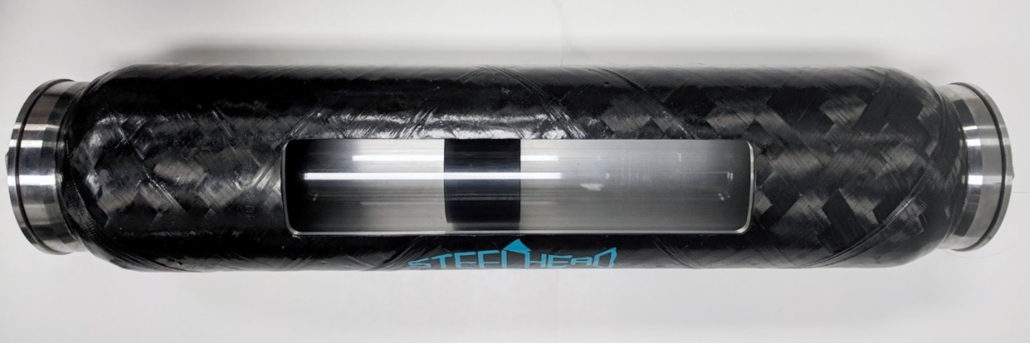
The design is structurally sound, and with minimal investment, could disrupt the propulsion industry with a safe, low cost, simple and efficient lightweight solution. The current technology readiness level is therefore relatively high at about 3/4. There are no material technical hurdles but there are significant testing requirements before the solution would be applicable to rocket propulsion. The potential payoff however, would be significant in terms of ease of use, cost and safety.
APPENDIX A. Steelhead CPPV Brochure